
Basic Electronics
All about electronics are here. Know the field of electronics which is majorly works on Chip design manufacturing and electronic system design.
Show moreThe country is not specifiedEnglish49 927The category is not specified
5 828Subscribers
No data24 hours
No data7 days
-630 days
Posts Archive
Basic formulas in electronics that everyone should know:
👉🏻Ohm's law: This is the fundamental relationship between electric current, voltage, and resistance. It states that the current flowing through a conductor is directly proportional to the voltage applied across it, and inversely proportional to its resistance. Mathematically, it is expressed as I = V/R, where I is the current in amperes, V is the voltage in volts, and R is the resistance in ohms.
👉🏻Kirchhoff's current law: This law states that the sum of the currents entering a junction in a circuit must be equal to the sum of the currents leaving that junction. Mathematically, it is expressed as the sum of all the currents entering a junction equals the sum of all the currents leaving that junction.
👉🏻Kirchhoff's voltage law: This law states that the sum of the voltage drops in a closed loop must equal the sum of the voltage rises in that loop. Mathematically, it is expressed as the sum of all the voltage drops around a closed loop equals the sum of all the voltage rises around that loop.
👉🏻Power formula: This formula relates the power dissipated in a circuit to the voltage and current flowing through it. It states that the power P in watts is equal to the product of the voltage V in volts and the current I in amperes. Mathematically, it is expressed as P = VI.
👉🏻Capacitance formula: This formula relates the capacitance C of a capacitor to its physical dimensions and the type of dielectric material used. It states that the capacitance is equal to the ratio of the charge Q stored on the capacitor to the voltage V across it. Mathematically, it is expressed as C = Q/V.
@BasicElectronics
Intermediate-level analog electronics projects you can try:
👉🏻Building a simple audio mixer circuit. This project will introduce you to the basics of audio mixing and how to use operational amplifiers (op-amps) to combine multiple audio signals.
👉🏻Making a simple digital-to-analog converter (DAC) circuit. This project will teach you about the principles of digital-to-analog conversion and how to use a DAC to convert digital signals into analog signals.
👉🏻Creating a simple automatic gain control (AGC) circuit. This project will introduce you to the concept of automatic gain control and how to use a simple AGC circuit to adjust the gain of an amplifier in response to changes in the input signal level.
👉🏻Building a simple frequency shift keying (FSK) modulator circuit. This project will teach you about the principles of frequency shift keying and how to use an FSK modulator to encode digital data onto an FM carrier signal.
👉🏻Making a simple capacitive touch sensing circuit. This project will introduce you to the basics of capacitive touch sensing and how to use a simple capacitive touch sensor to detect when a finger or other object comes into contact with a conductive surface.
@BasicElectronics
Beginner-level analog electronics projects you can try:
👉🏻Building a simple audio amplifier circuit using transistors. This project will introduce you to the basics of amplification and how transistors can be used to amplify a signal.
👉🏻Making a light-sensitive night light. This project will introduce you to the concept of photoresistors and how they can be used to detect light levels and turn a light on or off.
👉🏻Creating a temperature sensor circuit. This project will teach you about temperature-sensing devices and how to use them to measure temperature and display it on a simple digital display.
👉🏻Building a simple FM radio receiver. This project will introduce you to the principles of radio communication and how to build a simple FM radio receiver using readily available components.
👉🏻Making a simple burglar alarm circuit. This project will introduce you to the basics of digital logic and how to use it to create a simple burglar alarm circuit that can detect movement and sound an alarm.
@BasicElectronics
Intermediate-level projects that use Arduino:
👉🏻Building a digital clock using an Arduino, a 4-digit 7-segment display, and a real-time clock (RTC) module
👉🏻Designing a high-power amplifier using an Arduino, multiple BJTs or MOSFETs, and an audio amplifier IC
👉🏻Creating a touch-controlled lamp using an Arduino, a capacitive touch sensor, and an LED
👉🏻Building a remote control car using an Arduino, a motor driver, and a wireless module
👉🏻Designing a weather station using an Arduino, multiple sensors, and a display module
@BasicElectronics
Beginner-level projects that use Arduino:
👉🏻Building a simple LED blinking circuit using an Arduino and a breadboard
👉🏻Designing a temperature-controlled fan using an Arduino, a temperature sensor, and a MOSFET
👉🏻Creating a light-sensitive night light using an Arduino, an LDR (light-dependent resistor) sensor, and an
LED
👉🏻Building a water-level indicator using an Arduino, a float sensor, and a set of LEDs
👉🏻Designing a touch-controlled lamp using an Arduino, a capacitive touch sensor, and an LED
@BasicElectronics
Intermediate-level projects that use IoT (Internet of Things) in electronics:
👉🏻Building a smart home automation system using multiple sensors, microcontrollers, and Wi-Fi modules
👉🏻Designing a remote health monitoring system using multiple sensors, a microcontroller, and a Wi-Fi module
👉🏻Creating a smart security system using multiple sensors, a microcontroller, and a Wi-Fi module
Building a smart energy management system using multiple sensors, a microcontroller, and a Wi-Fi module
👉🏻Designing a remote environmental monitoring system using multiple sensors, a microcontroller, and a Wi-Fi module
@BasicElectronics
Basic projects that use IoT (Internet of Things) in electronics:
👉🏻Building a smart thermostat using a temperature sensor, a microcontroller, and a Wi-Fi module
👉🏻Designing a smart door lock using a fingerprint sensor, a microcontroller, and a Wi-Fi module
👉🏻Creating a remote monitoring system using a camera, a microcontroller, and a Wi-Fi module
👉🏻Building a smart plant watering system using a soil moisture sensor, a microcontroller, and a Wi-Fi module
👉🏻Designing a remote control system using a microcontroller, a Wi-Fi module, and a motor driver
@BasicElectronics
Intermediate-level projects that use sensors in electronics:
👉🏻Building a weather station using a temperature sensor, a humidity sensor, and a pressure sensor
👉🏻Designing a gas leak detector using a gas sensor and an alarm circuit
👉🏻Creating a smart plant watering system using a soil moisture sensor and a microcontroller
👉🏻Building a security system using a PIR sensor, a camera, and a microcontroller
👉🏻Designing a health monitor using a pulse sensor, an accelerometer, and a microcontroller
@BasicElectronics
Beginner-level projects that use sensors in electronics:
👉🏻Building a light-sensitive night light using an LDR (light-dependent resistor) sensor
👉🏻Designing a temperature-controlled fan using a thermistor sensor and a MOSFET
👉🏻Creating a motion-detecting alarm using a PIR (passive infrared) sensor and a buzzer
👉🏻Building a water-level indicator using a float sensor and a set of LEDs
👉🏻Designing a touch-controlled lamp using a capacitive touch sensor and an LED
@BasicElectronics
Intermediate-level projects that use transistors:
👉🏻Building a digital clock using a microcontroller and a MOSFET-based 7-segment display driver
👉🏻Designing a high-power amplifier using multiple BJTs or MOSFETs
👉🏻Creating a touch-controlled lamp using a microcontroller, a MOSFET, and a capacitive touch sensor
👉🏻Building a voltage regulator using a MOSFET and a Zener diode
👉🏻Designing a RF amplifier using MOSFETs or JFETs
@BasicElectronics
Beginner-level projects that use transistors:
👉🏻Building a simple electronic switch that turns on and off an LED
👉🏻Designing a circuit that amplifies an audio signal
👉🏻Creating a variable-brightness LED circuit using a MOSFET
👉🏻Building a pulse generator using a 555 timer IC and a MOSFET
👉🏻Creating a basic logic gate using a MOSFET or BJT
@BasicElectronics
A GAAFET (gate-all-around field-effect transistor) is a type of field-effect transistor (FET) that uses a gate that surrounds the channel on all sides. GAAFETs are a next-generation technology that offers several advantages over traditional MOSFETs, such as higher switching speeds and lower power consumption.
👉🏻GAAFETs are typically made using a multi-gate architecture, where the gate wraps around the channel on all four sides. This allows the gate to control the flow of electrons more effectively, resulting in higher performance and improved device characteristics. GAAFETs are also often made using novel materials, such as graphene or other 2D materials, which can further enhance their performance.
👉🏻GAAFETs are still in the development and research phase, and are not yet widely used in commercial applications. However, they have the potential to revolutionize the electronics industry by enabling faster, more efficient, and more compact electronic devices.
@BasicElectronics
Different types of MOSFETs:
Enhancement mode MOSFET: This type of MOSFET is turned on when a positive voltage is applied to the gate. It is commonly used as a switch in electronic circuits.
Depletion mode MOSFET: This type of MOSFET is turned on when a negative voltage is applied to the gate. It is commonly used in circuits that require a variable resistor.
n-channel MOSFET: This type of MOSFET uses an n-type semiconductor material, which means that it has an excess of electrons. It is commonly used in high-speed switching applications.
p-channel MOSFET: This type of MOSFET uses a p-type semiconductor material, which means that it has a deficiency of electrons. It is commonly used in low-power switching applications.
JFET (junction field-effect transistor): This type of MOSFET uses a pn junction to control the flow of electrons, rather than a metal-oxide gate. It is commonly used in low-power and low-frequency applications.
MOSFET amplifier: This type of MOSFET uses multiple transistors to amplify an input signal. It is commonly used in audio and radio frequency (RF) circuits.
@BasicElectronics
A MOSFET (metal-oxide-semiconductor field-effect transistor) is a type of field-effect transistor (FET) that uses a metal-oxide gate electrode to control the flow of electrons between the source and drain. MOSFETs are commonly used in many different types of electronic circuits and devices, including computers, smartphones, and other electronic devices.
👉🏻MOSFETs are known for their high switching speed, low power consumption, and high input impedance. They can be used as switches, amplifiers, or to control the flow of current in a circuit. MOSFETs are typically classified as either n-channel or p-channel, depending on the type of semiconductor material used.
👉🏻MOSFETs are widely used in many applications due to their versatility and high performance. They are often preferred over other types of transistors, such as bipolar junction transistors (BJTs), due to their low power consumption and high switching speed.
@BasicElectronics
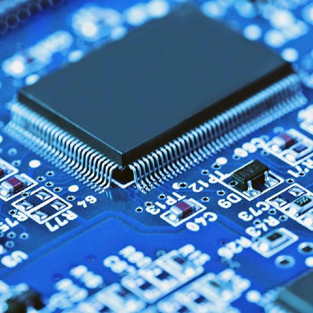
VLSI (very-large-scale integration) is a term used to describe the process of creating very complex integrated circuits (ICs) that contain millions or billions of transistors and other components on a single chip. VLSI circuits are used in a wide range of applications, including computers, smartphones, and other electronic devices.
👉🏻VLSI technology has made it possible to create highly complex and powerful electronic systems that are smaller, faster, and more energy-efficient than ever before. VLSI circuits are typically designed using computer-aided design (CAD) tools and manufactured using photolithography and other advanced technologies.
👉🏻VLSI design and development require a strong foundation in electrical engineering, computer science, and other related fields. VLSI engineers often work in teams to design, test, and verify VLSI circuits, and may also be involved in the manufacturing process.
@BasicElectronics
Commonly used ICs in electronic circuits:
555 timer IC: A versatile IC that can be used as an oscillator, pulse generator, or timer, often used in timing and clock circuits.
7400 series ICs: A family of digital logic ICs that contains a variety of gates, flip-flops, and other building blocks for digital circuits, commonly used in computers and other digital devices.
LM386 audio amplifier IC: A low-power audio amplifier that can be used to amplify small signals, often used in portable audio devices and musical instruments.
LM7805 voltage regulator IC: A linear voltage regulator that can provide a stable 5V DC output, often used to power microcontrollers and other electronic devices.
CD4017 decade counter IC: A digital counter that can count from 0 to 9 and then reset, often used in sequential circuits and display circuits.
CD4053 multiplexer IC: A digital IC that can select one of several inputs and route it to a common output, often used in data acquisition and control systems.
@BasicElectronics
Why Earth Pin of 3 pin plug is longer and thicker than other?
Earth pin is long for first to get connected so if any leakage to body of equipment from live line inside equipment will pass through the earth and person will safe.They are thicker to give more area of
contact so that leakage current will pass with less
resistance instead of passing through the working person.
AMBA
Advanced Microcontroller Bus Architecture
The ARM Advanced Microcontroller Bus Architecture (AMBA) is an open-standard, on-chip interconnect specification for the connection and management of functional blocks in system-on-a-chip (SoC) designs. It facilitates development of multi-processor designs with large numbers of controllers and peripherals with a bus architecture
@BasicElectronics
If you want to contact us
Message to this account
Username: @Ping_Admin_Now
Passive Attenuators
A Passive Attenuator is a special type of electrical or electronic bidirectional circuit made up of entirely resistive elements.
👉An attenuator is a two port resistive network designed to weaken or “attenuate” (hence their name) the power being supplied by a source to a level that is suitable for the connected load.
👉It reduces the amount of power being delivered to the connected load by either a single fixed amount, a variable amount or in a series of known switchable steps.
These are generally used in radio, communication and transmission line applications to weaken a stronger signal.
👉It is a purely passive resistive network (hence no supply) which is used in a wide variety of electronic equipment for extending the dynamic range of measuring equipment by adjusting signal levels, to provide impedance matching of oscillators or amplifiers to reduce the effects of improper input/output terminations, or to simply provide isolation between difference
@BasicElectronics
Lines of Force from a Bar Magnets Magnetic Field
However, magnetic flux does not actually flow from the north to the south pole or flow anywhere for that matter as magnetic flux is a static region around a magnet in which the magnetic force exists. In other words magnetic flux does not flow or move it is just there and is not influenced by gravity. Some important facts emerge when plotting lines of force:
✅ Lines of force NEVER cross.
✅ Lines of force are CONTINUOUS.
✅ Lines of force always form individual CLOSED LOOPS around the magnet.
✅ Lines of force have a definite
✅ DIRECTION from North to South.
✅ Lines of force that are close together indicate a STRONG magnetic field.
✅ Lines of force that are farther apart indicate a WEAK magnetic field.
@BasicElectronics
Why Earth Pin of 3 pin plug is longer and thicker than other?
Earth pin is long for first to get connected so if any leakage to body of equipment from live line inside equipment will pass through the earth and person will safe.They are thicker to give more area of
contact so that leakage current will pass with less
resistance instead of passing through the working person.
@BasicElectronics
Below you may subscribe and agree to the scheduled monthly payments to this channel.
What does CE marking on Electronic Device represent?
CE stands for Conformité Européenne. It's French for European Conformity.
CE marking is a certification mark that indicates conformity with health, safety, and environmental protection standards for products sold within the European Economic Area (EEA). The CE marking is also found on products sold outside the EEA that are manufactured in, or designed to be sold in, the EEA. This makes the CE marking recognizable worldwide even to people who are not familiar with the European Economic Area. It is in that sense similar to the FCC Declaration of Conformity used on certain electronic
devices sold in the United States.
@BasicElectronics
Join our other channels
And get the Best Content
For Basic Electronics : @BasicElectronics
For Python Learning: @Python_Codes
For Python Books : @PythonEbookz
For Knowledge: @TerrificKnowledge
For learning Basics: @BasicsToKnow
For Placements : @Aptitude_Tricky
What's Special Today:
@whatstodays_special
Udemy Channel: @udemy_channel
Quality Factor
The quality factor or Q factor is a measure of the performance of a coil, capacitor inductor in terms of its losses and resonator bandwidth. Simple formulas can relate the variables.
The definition of quality factor is often needed to give a more exact understanding of what this quantity actually is.
For electronic circuits, Q is defined as the ratio of the energy stored in the resonator to the energy supplied by a to it, per cycle, to keep signal amplitude constant, at a frequency where the stored energy is constant with time.
It can also be defined for an inductor as the ratio of its inductive reactance to its resistance at a particular frequency, and it is a measure of its efficiency.
@BasicElectronics
👋 Welcome to @realgroupforprogrammer 👋
In this Channel, You will get Udemy Free Courses, Free Coursera Courses, & FreeOnline Courses.
𝙁𝙤𝙧 𝙛𝙧𝙚𝙚 𝙘𝙤𝙪𝙧𝙨𝙚𝙨,𝙥𝙧𝙤𝙟𝙚𝙘𝙩𝙨,𝙞𝙣𝙩𝙚𝙧𝙣𝙨𝙝𝙞𝙥𝙨,𝙥𝙡𝙖𝙘𝙚𝙢𝙚𝙣𝙩𝙨 𝙖𝙣𝙙 𝙟𝙤𝙗𝙨 𝙧𝙚𝙡𝙖𝙩𝙚𝙙 𝙢𝙖𝙩𝙚𝙧𝙞𝙖𝙡 𝙖𝙣𝙙 𝙪𝙥𝙙𝙖𝙩𝙚𝙨 𝙟𝙤𝙞𝙣 𝙤𝙪𝙧 𝙩𝙚𝙡𝙚𝙜𝙧𝙖𝙢 𝙘𝙝𝙖𝙣𝙣𝙚𝙡:
https://telegram.me/realgroupforprogrammer
So what are you waiting for?
Join right now👍
https://telegram.me/realgroupforprogrammer
Opto-electronic (optical electronic) components
There are various components that can turn light into electricity or vice-versa. Photocells (also known as photoelectric cells) generate tiny electric currents when light falls on them and they're used as "magic eye" beams in various types of sensing equipment, including some kinds of smoke detector. Light-emitting diodes (LEDs) work in the opposite way, converting small electric currents into light. LEDs are typically used on the instrument panels of stereo equipment. Liquid crystal displays (LCDs), such as those used in flatscreen LCD televisions and laptop computers, are more sophisticated examples of opto-electronics.
@BasicElectronics